Tuesday, 29 May 2012

New thruster and vehicle design

Today I finished off machining a new thruster from 304 Stainless. Machining the stainless was quite dificult compared to the aluminium and mild steel I am used to. The new small boring bar was good but I went through 2 inserts in what was not allot of machining which was all I had. I really need to get good set of carbide tools as the ones I have dont seem to be lasting a long time (cheap ones from ebay). I broke too many inserts by not being patient enough.


I am happy with the engine as a first attempt but its heavier than I wanted (600 vs 400g) as I was conservative with wall thickness. I had designed for 3mm wall thickness but after spending hours working on it I was paranoid about cutting through the wall so I made it 5mm to be safe. The flange is also quite a bit thicker than I need it but I made it thicker so I could experiment with different clamping forces on the copper gasket. I allowed 1Kg for each engine in the vehicles design. Also I never seem to be able to get the bolt holes perfectly arrayed and there are always small mis-alignments (only goes together in one position).

I also made some parts to mount it to the test stand. This was a bit of a challenge because the inlet is on top of the injector plate as the thruster is designed to be bolted to a plate. I ended up making an adapter which makes the thruster all one size (size of the flange) so it can slide in a pipe which is fixed to the stand. There is then an inner free pipe which transfers force to the load cell. Both have slots milled in them at the load cell end at so the feed line can escape.


I really wanted to do a test later this week but Scott and Buren are not free until the weekend. After that I will start on a final revision. Hopefully we will get some good data this time.

 I am starting to build up momentum on the hovering vehicle front. We completely redesigned the frame after the original concept proved tricky to build. The old design had a frame made from sections of right angle aluminium which formed a triangle with plates to make it more rigid.

The tank was epoxied to the brackets which I was never particularly keen on. The whole thing was pretty complex and I was worried that it wouldn't be rigid enough so we came up with a new design which is much simpler and will be allot easier to build.


The new tank is now held between two plates with three thin aluminium tubes which clamps the plates to the tank. Electronics are not shown but I would like to have a second plate bellow the lower one so the electronics box can go between it and the upper plate.

The thrusters are brought in really close which makes landing gear not particularly effective unless they are a long way out which would be heavy. For initial tests we want to have the vehicle hanging so I am not even bothering with landing legs at the moment. One idea is a foam disc as shown in black in the concept picture, however I think it would be likely to tip over when landing. I am worried that the tether will mess with the control system. 

The vehicle will be initially pressurised to 500PSI leaving a safety factor of 1.9 which is much  less than that of the nirous tank we were going to use. If the vehicle had a bad fall the tank could rupture which would be really really bad. I think we will need to find a place other than the workshop to test. Padding around tank might help but I still want to be comfortable that in the worst case know-one will be injured. 

I started making the base plate yesterday and am fairly happy with how it turned out. It was pretty difficult to make as I had to plasma cut out the rough shape, mill it flat then linnish. I think I will try to find someone with a press brake for the rest. I would like to get a prototype frame mostly finished by the end of the weekend.


Saturday, 19 May 2012

I haven't been getting as much done as I would like to over the last two weeks but things are progressing and its about time I wrote an update.

I have been mainly working on the control system and have also been talking to a few people from UNI and other places about it but have gotten really mixed advice about how to develop it, which has really confused and bogged me down, to the point where I am not sure what to work on.


Choices are:
Do a really detailed simulation in CADAC++
Investigate a more optimal controller (LQR has been suggested) and use a more powerful micro controller.
Keep doing what I was planing on doing

What I was planing on doing is using a simple PI (turns out I don't need the D) and using simulink to program an arduino to demonstrate a proof of concept tethered stabilised vehicle; hanging or to the ground if that is too difficult.

I think the problem is my goals are not clear enough. The entire reason I started this project is to learn and programming a detained simulation in CADAC and learning about optimal control sounds like fun, however, if I did everything at a university/professional level I wouldn't get anywhere because it would take too long. I really need to decide if I want to do everything to a high standard or if I just want to get something that works. I could easily see my simulator talking to the deadline I set in June and I would probably be less motivated to work on it. Considering the amount of time and money I have put in and that I probably wont be able to work on it next year as I will be working full time I think I just need to get something working rather than study everything in depth.


 I have also started on an electronics box for all the flight electronics:


I gave some thought on how to package everything so that it would be still functional after a decent impact. Scott had the idea of mounting everything inside one box which was padded inside another. I liked the idea but it is a bit complicated so I just decided to pack everything in foam and have several levels of electronics stacked on top of each other. The top level isn't finished as I am waiting on some switch mode power supplies. Annoyingly I ordered some but they were only step up and wouldn't transform down. I am slightly worried that they will create noise which could interfere with the magnetometer on the IMU.

Also the miniature boring bar finally came yesterday which means I can continue work on the stainless thruster. I made a few attempts to make my own out of 1/8" square tool steel stock but none worked well enough. 

Wednesday, 2 May 2012

On Tuesday we tried a 30 second fireing of the 100N engine measuring thrust and chamber pressure. We diluted the peroxide to %85 so we wouldent have any issues with the silver melting over the long run. A few seconds into the test one of the nitrile gaskets broke which resulted in most of the peroxide leaking out and the engine pulsing wildley.


Despite the engine only running propely for a few seconds we good some good data. I still havent calbrated the load cell propelly but it looks like it produced about 60N. I am not sure if this is because the engine hadent warmed up yet, or because the throat needs to be enlarged more. Engine pressure was 120PSI at its peak which is alright but I would like it at 200PSI.

So we really need a new design of seal. I have been looking at Armidillo’s engines and it seems that they use copper gaskets. I suppose it makes sense that a somewhat flamamable rubber seal (nitrile) which is heated to 800 degrees and exposed to peroxide would fail. The odd thing is that the gasket worked fine for the last test which was much longer than this one, although it did look slightly burnt/warped. Looking at the video it seems that the gasket actually popped out rather than burning through. Also when we took the egnine apart it wasent actually broken. My guess is that the engine bolts wernt as tight as it was for the first test.


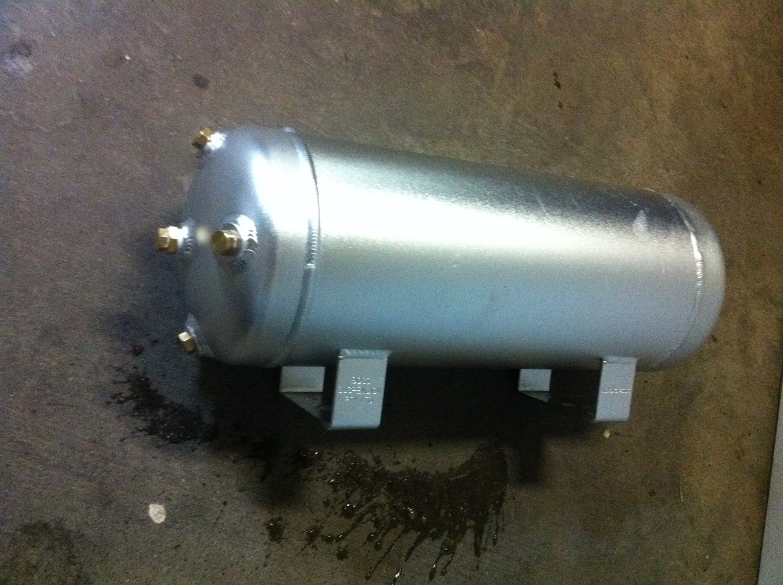
In other news I found a great new tank which will make for a perfect flight tank on the hovering rocket as it is holds nearly the same volume as the heavy nitrous one (10L) and only weights 2Kg! Its designed for compressed air in automotive applications and is only rated to 200PSI but I figured it would have a generous safety factor so I got one to test. It also has holes on its top and bottom which means we could do without vacuum filling which is another bonus.

We hydro tested the tank and found it to burst at 950PSI. My previous method of hydro testing is hydraulic pump, however it runs on oil and makes a mess so I tried another method of using air from our high pressure cylinders and a regulator. I figured that because the tank was filled with water the failure wouldent be particularly catastrophic, however I think that some of the nitrogen dissolved in the water because when the vessel ruptured it made quite a loud sound. It was in the peroxide bunker (where we used to concentrate the peroxide) so I dident do any damage but it gave everyone quite a fright. The resulator method was good because I could slowly increase the pressure as opposed to the jack which required allot of force and usually vessels fail when applying force and when you are not looking at the gauge.

I still want to test one more tank to failure to ensure the failure mode is the same before we incorporate it into the vehicle. The vessel seems to have failed at one of the leg welds which is a bit unexpected as we all thought it would fail at the cap welds, but makes sense as the stress in the cylindrical section is double that of the hemispheres and the leg weld would have weakened a small part of it. The crack seems to have travelled down the tank to the other leg which would have been the next point of stress concentration. When you look inside you can see discolouration from the leg weld. I will film the next test with my high speed camera which should give us a better idea of what happend.

Assuming the next vessel fails at around 950PSI I will feel comfortable using the tank at 500PSI which is what we were going to use the nitrous tank at. The tank has 5 fittings in it, 4 on one end and one on the other. The 4 fitting end will probably go on the top of the vehicle. I am slightly worried about what would happen if the vehicle fell from a decent height and the tank took the impact causing it to rupture. I think we will meed to find a larger location to test at. I was actually thinking that we could pressurise the vehicle remotely so we dont have to be anywhere near it.


As for the vehicle, my goal is have it ready for a tethered test by the 25 of July  which is about 11 weeks away. My original goal was 6 weeks but that would be the middle of exams, and the holidays will provide a good time to bring everything together. I am confident we can get everything together before then.

Sunday, 29 April 2012

I did some work on the simulator today. The simulator had a bunch of bugs in it mostly due to the coordinates of the simulator and visualisation not lining up. Under certain situations the vehicle would not go in the direction you would expect it to.  Fixing this was not as straightforward as I initially thought as there were lots of places in the simulation I could account for offsets and rotations; most having unintentional consequences. I have never worked on something so counter-intuitive and difficult to get a hold of.

The simulator now has realistic mass and moments of inertia and I can control it with the joystick just by commanding roll. The pid outputs from roll and pitch are also combined intelligently to produce pure roll and pitch.

Unfortunately although being good at responding to desired roll and pitch inputs (step inputs) the PID's cant cope at all with uneven thruster forces.

I tried using both the trigger (Armidillo style) and slider throttle to control thrust but the throttle seemed much better. It does mean that it will be harder to shut off in an accident.

I tried varying the thruster position away from the centre between 0.4 and 1m. The vehicle was definitely more responsive for farther positions but was still easily controllable at 0.4m


Perhaps the most exciting thing I discovered is that sinulink can compile code that  can run stand alone on lots of different micro controllers! This is great because I wont have to implement the control system on a micro controller which is something I wasn't looking forward to doing. What's even better is that it can communicate with simulink running on a computer to display information, so I can interface the joystick directly to it and display gauges and other impressive looking but useless widgets! (I am considering a star trek theme). I plan on starting with an Atmel and going to a beagle board if I need more power.

If I can get the thruster unbalance correction working well then I think I will be ready to start working on the real thing. I think I will need to somehow account for thruster unbalances directly before the PID.


Saturday, 28 April 2012

We were planing on testing the thruster again today but since it is raining heavily we decided to postpone to Tuesday

I am still looking for a suitable reamer, I am not sure I will be able to find one so might have to settle for a small (5mm) boring bar. This should be able to cut the divergence with a 8mm throat.

I think I now have a good handle on the dynamics of the vehicle. The problem is that each motor produces torque in pitch and roll, and the way the control system is working now there are 2 PID's taking pitch and roll and outputting one thruster force. It works but not very well. A friend commented that the vehicle was allot like the 3 wheels omni drive robots we made in high school and he is right, what I really needed to do was think in terms of vectors. What I couldn't understand was how I could take two outputs (one from roll and pitch PID's) and transform that into three motor forces. Well it seems obvious now that I just need to have an expression for  roll and pitch, and to just think about the PID's output as a desired moment (although I an not sure what they are). I was sort of doing this before however I got really confused about how the PID constants matlab choose varied depending on if I was commanding "pure torque" to the vehicle or interpreting it as forces which then later got converted back to toques to make the simulation realistic.

Up until now I had been using a simple extruded triangle to represent the vehicle in the simulation. I finally managed to convert our solid edge assembly file of our protype to a VRML file via IGES. It was a huge pain but I finally got it working only to find that VRML viewer built into simulink couldn't render it fast enough (because it is too complicated). It was made in 1997......

So I had to remake the vehicle with simple shapes and while I was making it I thought, why are the engines so far out? Well I couldn't think of a good reason except they night have to be to get the control we need, but from my limited simulator experience I have found that very small thrust variations can induce large rotations quickly. In addition our current design is needlessly complicated. The original plan for fixing the tank to the vehicle was to epoxy brackets to the nitrous tank. I have had some second thoughts about that, mainly because it is a permanent solution. I have come up with a much simpler design:


The basic concept at-least is to bring the engines in as close as possible (model is really only for simulation purposes). We will probably need to have two  triangular plates separated with spacers between which can sit the valves and electronics. The tank can sit upside-down and its neck protrude through the first plate (with syphon removed). We can then have one plate on the top of the vehicle (bottom of tank with threaded rod to clamp the tank to the vehicle.


Tuesday, 24 April 2012

Simulator, New engine machining

Today I started machining up the new engine out of 304 stainless. I have never machined stainless before and for some reason I thought that it was going to be really difficult but as it turns out it wasn't too bad. I prefer aluminium or brass where possible but stainless does have some advantages;  unlike brass it doesn't break up into millions of tiny fragments which give you splinters. I have heard that 316 stainless is worse.


The stainless stock I has was 60mm diameter and as the actual chamber is only 26mm in diameter there was quite a bit to take off. The reason I got such a big piece was that we weren't sure how big to make the flange. As it turns out the flange doesn't need to be very big if we have a radial o-ring instead of a gasket/face seal. This design also saves weight. I was tempted to go with a design that diffident have any flange, only radial bolts to secure the thing, but because it is already so small a flange is really the only way we are going to be able to mount the engine to the vehicle. We are going back to top injection because on the vehicle we can just have a hole on the mounting bracket for the line to go through.

One issue I had was trying to cut the divergence for the nozzle. For brass and aluminium I use a special tool I made which has the divergence profile in it. It is made from soft steel and was not able to cut the stainless. What I really need is a tapered reamer however I have not been able to find one with the right angle. The other option is to get a big piece of tool steel and remake the tool.


Because I wasn't able to cut the divergence I thought it was pointless continuing on the new thruster as machining the 60mm stock to 26m is allot of work. I am looking for a tapered reamer which might take a while to get here. In the mean time I can get some smaller stock.


We still need to test a long duration firing so we can start work on the vehicle. Because we wont have the stainless thruster for a while we will need to make do with the brass one. I modified the test stand so it could be used with the load cell and drilled a hole at the bottom of the chamber so we could insert a pressure tap and measure chamber pressure. Hopefully this weekend we can do a 30 second firing and get good pressure and thrust data. The throat is currently 6mm which is a bit small for 100N so we might not get as much thrust as I wanted. The peroxide propulsion spreadsheet says 8mm but that's with a much lower feed pressure so we will see.

Simulator progress is going well. I have added in joystick functionality so I can command roll with it. I dident realise it before but the way the control is now the roll pitch PID's each only controll one thruster. This means that it is able to stabilise only using two thrusters but the system response is coupled so you cant have pure roll and pitch. This also seems to also induce a yaw.  One way to fix this would be for the output of the pitch and roll to be a torque which I could then convert to a thruster input.

Sunday, 22 April 2012

The plan was to test a new stainless light thruster yesterday but that diffident end up happening as Buren had a class and Scott was busy. The simulation is going fairly well, I now have a nice 3d model which falls under gravity and has basic roll control via PID control that can correct for misalignments in starting orientation. I have found the biggest challenge is working with the coordinate system and trying to understand if it is behaving as it should. Ariel seems to think that countering gravity should be the main task and roll control should then come in, which will stop the vehicle loosing altitude wheel translating. This involves either having an estimate for mass which is always changing, or minimising vertical acceleration. I think this is too complicated and think that roll control should come first. For manual control this is probably the case but I am not sure for automatic control.

The first task I would like the vehicle to perform is a basic hop. That will mean throttling up until it senses positive acceleration, throttling to achieve neutral acceleration while travelling up for a period of time, throttling down for negative acceleration then maintaining till it detects positive acceleration via impact with the ground. All the while the roll control will need to stabilise the vehicle.

I am still unsure weather I want to peruse manual control like Armadillo did. After I get basic hops working I suppose I will want to get translational motion working, which without a joystick will involve some positional sensors. GPS is really appropriate for the small distances the vehicle will be travelling and a range finder for height will be quite expensive. Manual input would bypassing the need for any absolute sensors.

I really need to machine up the new engine and we need to conduct a ling duration firing so we can start on the vehicle. By the time this is done the simulation should be at the point where we can see what geometries are optimal.