We have a new member to the group. Bart Hertog is a control systems engineer living in the Netherlands. Bart will be working on the vehicles control system and implementation.
Bart has designed a system that is based on two PI loops for roll control. There is a inner velocity loop that takes roll rate and an outer position loop that takes absolute position.
The plan was to test/tune the velocity loop on Sunday (yesterday) but after a full day of programming on Saturday I was tired, frustrated and starting to make mistakes so I decided postpone a week rather than rush to test something that was not ready.
Bart also had a really good idea to stop an auto hover if the roll/pitch became greater than 45 degrees. This is a really good safety mechnism.
If you think of the output from the control loop as a desired torque the main problem so far has been how to best convert the torque into 3 thruster forces in a way that maintains the desired thrust and also stays within the limits thrust that the thrusters can actually produce. Also the fact that we don't know exactly how much thrust the thrusters can output doesn't help.
We still need to make a proper battery mount to avoid the last minute duct tape we used after the battery came loose last time.
Buren has re-made the remote quick-disconnect with two solenoids which seems to work well so we shouldn't need to use the line cutter for the next test. He has also made a counterweight system so the solenoid and line will be automatically pulled to the top of the test stand after it is disconnected from the vehicle.
Nick is currently looking into a RTK gps system. He wanted to use a beagle board as the fixed base station but I would prefer to just use a computer. We will probably want to get another data modem just for the RTK system.
Sam is working on the control GIU which sends strings out via serial.
Sunday, 9 September 2012

Tuesday, 4 September 2012
Laser Rangefinder
Determining altitude is trickier than it may seem. An IR range finder will not work due to the heat of the engines and ultrasonic wont work because of the noise. The only real options left are Radar or a laser.
I have looked lots of laser range finders but they are all either expensive or not suited to my application. There are plenty of cheap "laser tape measures" but all display the distance on a built-in screen and attempts by others to modify them have been limited to hacking the segment display. Parallax make a reasonable priced sensor but it uses triangulation (with a camera) instead of time of flight and I think that the cloudy exhaust might interfere and also only works at 1Hz. There are heaps of industrial ones but none under 1K$.
Today I came across this:
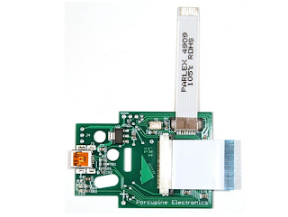
Its a board by Porcupine Electronics that connects to a fluke 411D (laser range finder) and outputs the distance data over USB and serial.:


I have looked lots of laser range finders but they are all either expensive or not suited to my application. There are plenty of cheap "laser tape measures" but all display the distance on a built-in screen and attempts by others to modify them have been limited to hacking the segment display. Parallax make a reasonable priced sensor but it uses triangulation (with a camera) instead of time of flight and I think that the cloudy exhaust might interfere and also only works at 1Hz. There are heaps of industrial ones but none under 1K$.
Today I came across this:

Its a board by Porcupine Electronics that connects to a fluke 411D (laser range finder) and outputs the distance data over USB and serial.:

The display and keyboard is removed and replaced

Apparently it can output at 10Hz with +- 3mm accuracy from 10cm to 30m. Also it will be quite light as the housing can be removed and the electronics themselves wont weigh much.
Saturday, 1 September 2012
Data Data Data
As it turns out the reason the plots of roll and pitch (refer to last post) looked so strange is because the script I wrote to extract them from the log file couldn't handle variable length strings and as such had a preference for positive numbers. Here is what it should look like:


As can be seen the amplitude is highest at about 100Hz and 250Hz. I these are natural frequency of the speaker/housing? I am also not sure what filtering the speakers do so its possible that they filter out certain frequencies.
Because the amplitude of the vibrations vary so much I don't think any firm conclusions can be drawn but it is clear that there are some frequencies that affect the IMU more than others. Keeping in mind that the IMU was experiencing some fairly severe vibrations in excess of 2G's at peak (it was a really big subwoofer) I am happy with how it performed.
An improvement for future work would be to compensate for amplitude by scaling the raw accelerometer and data (dont think you need to change gyro data) however I am not entirely sure how you would do this in a way that didn't mess up the DCM algorithm that calculates orientation. An alternative would be to use a more consistant vibration source.
Also the test I had planed on doing tomorrow has been canceled because Buren and Sam couldn't make it. Its probably just as well because I still haven't implemented the basic roll control I wanted to test and there will be lots of bugs to fix. I have made a basic test platform which consists of 3 LED's to simulate the engine so we can see if all the axis/directions are right.

I have also been doing some vibration testing of the IMU. One of my main concerns is that the vibrations from the solenoids/engine thrust will mess with the IMU's measurements. My first thought for generating vibration was to use a vibration motor but I didn't have one handy and I couldn't find any information on the frequency of my mobile phone vibrator so I used a large speaker (subwoofer).
Here is a plot of roll and pitch with the IMU on the speaker housing with a sine wave sweep from 20-300Hz. When stationary roll and pitch have an error of about +-0.3 degrees.

Sin sweep from 10-100Hz (horizontal scale is wrong):

I noticed that some frequencies sounded much louder than others. At first I thought this was because the ear filters out some frequencies but feeling the enclosure some frequencies definitely felt like they had a higher amplitude.
I used a iPhone app called "Vibration" to measure the amplitude of the speakers vibration (20-300Hz) which can be seen bellow (vertical axis is G's). The other option was to get the IMU to output raw acceleration data.

As can be seen the amplitude is highest at about 100Hz and 250Hz. I these are natural frequency of the speaker/housing? I am also not sure what filtering the speakers do so its possible that they filter out certain frequencies.
Because the amplitude of the vibrations vary so much I don't think any firm conclusions can be drawn but it is clear that there are some frequencies that affect the IMU more than others. Keeping in mind that the IMU was experiencing some fairly severe vibrations in excess of 2G's at peak (it was a really big subwoofer) I am happy with how it performed.
An improvement for future work would be to compensate for amplitude by scaling the raw accelerometer and data (dont think you need to change gyro data) however I am not entirely sure how you would do this in a way that didn't mess up the DCM algorithm that calculates orientation. An alternative would be to use a more consistant vibration source.
Also the test I had planed on doing tomorrow has been canceled because Buren and Sam couldn't make it. Its probably just as well because I still haven't implemented the basic roll control I wanted to test and there will be lots of bugs to fix. I have made a basic test platform which consists of 3 LED's to simulate the engine so we can see if all the axis/directions are right.
Saturday, 25 August 2012
IMU Data from flight
Today I wrote a script to extract the useful bits from the log files recorded during last Sundays test
Bellow is a plot of Roll and Pitch for the second test (the first one in the video(one where its still light)). The sample rate was about 50Hz. When the IMU was shocked too severely it gives really high values so I filtered out any values higher/lower than +/-180. From what I can see the only times the IMU gave wrong values was when it was bouncing on its tether. The values didn't seem to be affected by any engine vibrations although I wasn't pulsing the engine (was on full). During the static tests the vibration while pulsing is much more severe. I have been doing some research on the vibration sensitivity on the Arduimu's MPU-600 (gyro and accelerometer) and the chip should be able to handle the low frequency (30Hz) vibrations from the solenoids fairly well as long as the amplitude is reasonable because the MEMS accelerometers work at much higher frequencies (in the KHz).

You can see the point of liftoff in the middle where the roll and pitch peaks. All the oscillations are when it is rocking around on its tether.
Looking at the graph you can see that the IMU has a preference for positive values. There is a problem with some newer ArduIMU's where the manufacturer of the MPU-600 (gyro and accelerometer) changed its gyro scaling values and as such rolls and pitches appear exaggerated and wrong. The firmware I was running during the flight was older and I don't think had the new value so I dont think this is the cause of the problem. I really need to do more playing with it.
Monday, 20 August 2012
First teathered flight test
Yesterday we flew the hovering rocket for the first time. I am still working on the stabilisation program so it was controlled just by pulsing all the thrusters at maximum which resulted in a crazy looking flight.
We actually did 3 separate tests. The first one was a practise run with water to make sure everything was working. Then we did a test with peroxide but after the first hop (if you can call it that) the battery came loose so we stopped the test. We then replaced the hose and did a second test. It was quite dark by this stage so it is a bit difficult to see what it happening in the video. Here is short video showing some of the test:


My objectives for the test were:


We actually did 3 separate tests. The first one was a practise run with water to make sure everything was working. Then we did a test with peroxide but after the first hop (if you can call it that) the battery came loose so we stopped the test. We then replaced the hose and did a second test. It was quite dark by this stage so it is a bit difficult to see what it happening in the video. Here is short video showing some of the test:


My objectives for the test were:
- Test the ground, flight command and data logging systems.
- Demonstrate that the vehicle could actually liftoff.
- Record orientation data to see how the ArduIMU coped with the flight
I had a fairly hectic saturday trying to get everything finished in time. I decided to redesign the disconnect system as it doesn't quite work as well on the vehicle as it did on the bench tests. The reason for this is that if there is any torsion on the disconnect it takes much more force to actuate and the solenoid isn't able to provide enough force.
Instead of the quick disconnect I decided to go with a more reliable system which involves cutting the pressurisation line. To cut the line I used a set of electric shears and modified them to be actuated remotely. I was really surprised by how complicated the control electronics of the shears were....

Test of the system:
For this feathered test we cut the line on the ground. The idea was for the coiled air hose to recoil so there wasn't much hanging off the rocket. Unfortunately the hose didn't recoil much so there was hose flailing around on the side of the rocket during the test. For the next test plan on cutting the hose just above the solenoid with the cutter on a trolley leaving minimal hose remaining on the rocket.
For this test we only pressurised the vehicle to 450PSI as the cheap hardware air hose we used burst at around 500PSI. Unfortunately I was at work and Buren didn't get to the fitting store before it closed to get thicker nylon hosing.
There were quite a few issues with the command system. A few times when I would command a pulse of all engines one would stay on after it should be off for a few seconds which was quite concerning. Also the vehicle didn't respond to a few of the pulse commands which I think is because it is trying to send too much data (every time it gets a new IMU update) so misses the ocational command. I think that this might be the cause of one engine staying on too long as it gets stuck sending data. I either need to get a separate radio for commands than for data or log the sensor data in HD onboard and only send data back occasionally. On a side note I was rushing on saturday truing to get everything ready and I fried the Arduino by reversing the voltage in. Luckily I could get another one locally but they didn't sell the exact same one, instead I got one based on a Atmega2560 which also has a micro-sd port and a lan port. I didn't have time to learn how to use the SD port but should be using it next test.
All the ground systems worked really well. I edited this tool which displays the orientation of the rocket (currently a picture of a plane) in 3d and also pressure in real time and allows me to send text commands I type in (I didn't have time to put in buttons....). The pressure transducer didn't work but I didn't have time to figure out why. It also logs the data and displays them in the program. This was the first time I have used the processing language and maybe its the mechanical engineer in me but I love it! I haven't looked at the orientation data propelly (need to make a program to re-play it from the log) but from looking at the screen during the test and the text log it seems quite smooth and doesn't jump around much. The vent solenoid seems to interferer with the yaw (as it uses the compass sensor) but I don't need yaw. I need to have a better look at the arduIMU firmware. I increased the arduIMU's output rate from about 5hx to 50hz but I think the way I did it might have messed up something else as even when I am holding it still the roll and pitch seems to be rougher than it was before.

We were all a bit disorganised at the test and there are a bunch of things to improve for next time. I wasn't particularly happy there were things we hadn't thought of in advance. Sam started to do an operations manual for the test but it wasn't finished to the point of being useful and we didn't all have proper roles.
I am happy with our filling and pressurisation system, its the safest system yet. Briefly: The vehicle is filled using a funnel in the clean space of the workshop and then is carefully carried outside without the pressure relief plug installed so it is open to the atmosphere. We then set up the disconnect, cameras etc. and everyone but me goes away. I then turn on the computer, test it and arm the failsafe vent solenoid. On a side note I put a really bright light on the vent solenoid so I could see when it was on so there is less chance of leaving it on and burning out. Lastly I install the pressure relief plug so then vehicle is sealed.
So there are a heap of things to improve before the next test. I cant see us being ready for an active stabilisation test this weekend but we should be ready the week after.
Sunday, 12 August 2012
Delayed Test
Yesterday I planed on doing a basic test firing of the thrusters to check if everything was woking before starting to tune/test our control system. Unfortunately we didn't get that far because I fried all 3 solid state relays by wiring them backwards. I figured that because they were switches it didn't matter which way they were wired. As it turns out they are not just switches....
Instead we did all the other things needed required for a hanging test. I am going to pick up some replacement relays locally which should work (they are rated for a minimum 24v and I am using 12) . If not I will have to wait a while for new ones.
In order to retract the pressurisation tube and quick disconnect after pressurising we are going to use a simple pulley system which pulls the line and electrical cable off to one side of the stand.
For the pressurisation and venting I decided to go with simple hard wired electronics instead of a separate micro controller which would be triggered by the computer.


Instead we did all the other things needed required for a hanging test. I am going to pick up some replacement relays locally which should work (they are rated for a minimum 24v and I am using 12) . If not I will have to wait a while for new ones.
In order to retract the pressurisation tube and quick disconnect after pressurising we are going to use a simple pulley system which pulls the line and electrical cable off to one side of the stand.
For the pressurisation and venting I decided to go with simple hard wired electronics instead of a separate micro controller which would be triggered by the computer.


This is the quick disconnect sam made a while ago. It looks a bit crude but works every time.


Wednesday, 8 August 2012
Vehicle Progress
On sunday Burren finished the remaining plumbing and we leak tested everything to 120PSI. There were a few small leaks but we tightened the leaking fittings which fixed them. I didn't feel comfortable pressurising the tank any higher than 120PSI with us around. On sunday I want to do a complete practise run with water to test out all the systems and also see if there are any leaks at higher pressures. Electronics are now %90 finished, I just need to wire up the fail-safe pressure relief solenoid. This is a normally closed (on) relay wired to the solenoid so the solenoid will be open when the controller is not telling it to stay closed. A mechanical solution would be ideal but I cant find any normally open solenoids that suit our application. We will just have to be careful about checking battery voltage before each test.
If the systems test on sunday goes well I might also try a quick (unguided) run on the test stand. We assembled the lighting truss last night and although it is not quite as sturdy as I was hopping it should work well. As a friend pointed out might need to weigh down the sides to stop it falling over.
I managed to burn out the vent solenoid the other day by leaving it on for too long. They are not designed to operate continuously and get extremely hot when operated continuously for more than 30 seconds. As a friend pointed out they take about 9 amps to run so at 12 volts with P=IV they are dissipating more than 100w of power! I took the burnt out solenoid apart and found that one of the wires to the coil had melted. I re-soldered it but because the coil had heated up so much the enamel on the copper enamel wire had flaked off so it was shorting somewhere inside and as such the resistance was negligible and so was like a short circuit and it melted the again. You can buy replacement coils but I didn't want to wait for one so I intend to re-coil it myself. The solenoid would be able to dissipate the heat much better except that the coil is wound on a plastic bobbin which insulates it from the heat sink that is the solenoid body. I intend to re-wind the solenoid directly to the solenoids steel shaft which will allow the heat to be conducted to the solenoid body. I was toying with re-winding with thicker wire to lower the resistance then make up the difference with a power resistor or possibly just running it at a lower voltage. The lathe made it really easy to unwind the coil.


Subscribe to:
Posts (Atom)