Saturday, 23 July 2011

Finished valves, nearly ready for a test

Today I finished up the last of the electrical work to get the valves connected. After that I played around with the timing to open and close them, and also trying to get them to reliably go to specific positions. Unfortunately the two valves are not the same (one is geared almost double) so they require different times to actuate. I made the key to couple the plate to the motor shaft out of soft aluminium so that if it tuned too far it wouldn't rip itself apart (the motor and gearbox has about 150Nm of torque). I broke a few keys at the start but didn't break any after I got better at the timing. I was worried that the minium time required for the relays that control the motors would be too big to get fine control of the valve position but it seems as if I can get at least a 100ms pulse. I am having this wired problem where the motor would rotate more in one direction that in the reverse, even though it was being pulsed for the same period of time, which I am yet to solve. There is a small amount of play in the position, which i think i should be able to at least improve by using a Steel key. Also something to improve would be putting limit switches on the motor, as i am worried about a key breaking during a test and having limited control. I will do a few dry runs and if its an issue I will have to add them. I am not really confident in the valves ability to hold its position after a few movements, after about 4 movements I would not want to rely on it being where it should be. For the first test I really only need three positions, closed, 1/10th for startup and full open so the accuracy won't be that big of an issue.


Also I have started thinking about the startup sequence, which felt odd at first because for the most part there has been little theory and a lot of time consuming fabrication. I plan on using a pyrotechnic igniter because its simple, reliable and I believe will limit the possibility of unburnt propellant collecting and causing a hard start. I have two ideas for igniters, a thermite based igniter and one based on a cylindrical strand of solid propellant. The thermite based one has the advantage that it is more energetic and will throw sparks increasing the chance of ignition. The solid propellant one although not as energetic and having a smaller burning area will increase the chamber pressure to (if sized correctly) operating pressure. I am worried that because of the large initial pressure differential and the inability of positing the valves with precision that the starting propellant flow will be too large. Pressurising the chamber will reduce the chance of a large volume of propellant entering the chamber causing a hard start. The igniter will need to burn for at least 5 seconds, but the longer the better. The other advantage of thermite is that its burn rate not really sensitive to pressure, whereas too much solid propellant could in itself cause a  hard start.

After the igniter has started burning and visual confirmation of the burning has been acknowleged I will open the fuel and oxidiser valves to 1/10th or thereabouts. Form what i have read its better to have a fuel rich flame so the fuel valve will be open more than the oxidiser one. Once I have visual confirmation of the propellant burning I will open the valves to full. Once the chamber pressure is right it shouldn't really matter how open the valves are. I am still not really sure I understand why the chamber pressure settles to a particular value, dependant on the feed pressure (as the flow through the injectors isn't choked) . Thats something I would like to understand better. Whenever I try to think about it I go in circles because the chamber pressure is dependant of the mass flow which is dependant on the chamber pressure. I understand that with a fixed exit area the pressure will reach an equilibrium but how would you possibly calculate that? More reading required.....


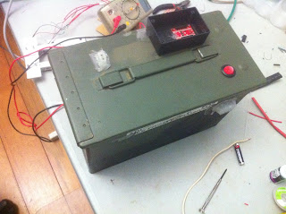
Anyway so I am pretty much ready to go for a first test. All I am waiting for now is a location. Next I will run some full duration tests with 750PSI and make a few igniters to test. Good igniters will be a evolutionary process as i can't really test them properly without a firing. I will try firing a igniter while flow testing with water to see how the flow rate changes but the water will probably mess with the igniter. One other think I need to do is drill a hole in the chamber for the pressure transducer. If i have enough time before a location is found I will start working on having electronic sensors which are transmitted via telemetry (which i will need to do before a second test anyway), otherwise a pressure gauge and a camera will have so do. Sensor data (in particular pressure) would be very useful for knowing whats going on in the chamber but its not necessary. For the first test all i really want to so is a few 5 second runs. Also here is a few pictures of various parts. Since taking the batteries out of the relay box I remounted everything and its a lot neater now. The cooling jacket is on the chamber (only one of the two barbs in currently on). You can see little bits of oring coming out, but it holds pressure and doesn't need to so I am not really worried. See if you can guess what the last picture is of.


Thursday, 21 July 2011

Slow testing injectors, New battery

Yesterday I assembled the load and two injector plates and tested the combustion chambers injectors for the first time with low pressure water (250PSI). Everything went smoothly and there did not apear to be any leaked from the injectors o-rings. I ran out of thread tape towards the end so I just went without which resulted in me getting quite wet. I didn't take too manny photos because of that. Also yesterday I went to a local garage and managed to get two quite good car batteries they were getting rid of which i am now using to power the test stand.I am always amazed at the perfectly good things people throw out, and in the case of car batteries as soon as the car wont start most people go straight to a new battery, and mechanics are more than happy to sell it to them. I had to hold back my entrepreneurial side from getting lots and selling them! I am now running the test stand completely from the computer which is really satisfying.

Tomorrow i want to work on the electric valves. This will involve installing their relays, making a few spacers and modifying the program for the new inputs. I am unsure exactly how controlling the valves by pulsing them on and off will work, i may have a few buttons in the program, an arrow or a entry fiend where you enter the number of seconds you want the valve to turn for. I will do some experimenting to see waht works best. After i get those working i will do a high pressure flow test (don't want to go past 750PSI while i am anywhere near the tanks) so i may drive somewhere to test out how the trailer performs on road and what comes loose. After that i will be pretty much ready for the test. At the moment i am only waiting for a test site. The site we were going to use at Warrack fell through and i am currently waiting on a response from a few others who may be kind enough to let us test at their remote properties. It would be really nice to test this weekend but without anywhere to test thats not going to happen.

I did have a crazy idea to buy a small lot of land a few hours away from brisbane. There are some places for as low as $5000 for 10's of hectares about two hours drive. Most of them are sold as opal fossicking  sites so I am not really sure if i would own the land or just the rights to mine on it. For a step up in price ($10000) you can get a small freehold piece of land. I was looking at one 12 Hectare lot near esk. Really it doesn't matter how big the land is as long as there is nothing around so as long as i can use the mining site for whatever i want it should do nicely. I would be more tempted if i could justify it as an investment but but realistically a verry small property in the middle of nowhere wont appreciate and will be very difficult to sell if i ever wanted to. Also the cheap lots are very hilly and only have 4WD access though neibouring lots. This might make getting equipment (shipping container for example) difficult. I know its a pretty radical solution to the problem of not having anywhere to test but it would have lots of advantages.

Also when at repco today i found a interesting source of cheap high pressure flexible hose. Its grease gun hose and its rated to a surprisingly high pressure considering it only carries grease (5000PSI). I am not sure how compatible it would be with nitrous oxide but I always get excited when i find a source of  a new material i have been looking for!

Tuesday, 19 July 2011

I started washing out the run tanks today. I first washed the nitrous tanks twice with water to see how much oil there was in there. There was not too much, but a definite layer on top of the water that came out. The second time there was much less. I then washed them out with detergent three times before the power supply i was using to power everything died. I got a bit wet the first few times opening the wrong valves when there was water in the tanks and having it spray out at me under high pressure. One problem I had was that the solenoids would get very hot after a minute of continuous operation. Turns out they are not designed to operate continuously and draw allot of current, 8A to be exact. This is only of concern for the main pressurisation solenoid as the other two will not be operating for long periods of time. I may have to pulse it to avoid overheating it. I had also been having a problem with the batteries in the relay box not having enough current. Today i found out that when charging one would get quite warmer than the other. It was also the one that was upright (other one was horizontal). I was under the impression that sealed lead acid batteries could be used in any orientation, and that is true but the batteries I have are not sealed despite their appearance. I think they are "imitation" SLA's as they have this plastic plate glued over the acid wells. I am not really sure what to do. New batteries will take too long and i am not sure that they will have a large enough capacity after finding out how much the solenoids draw. I think i might go to some auto electrical places tomorrow and ask if they have any old car batteries. The other annoyance is that with the power supply that died today i only have a small 2A supply with which to charge the batteries with that low current it takes much longer. I am now fairly happy with the plumbing so i should be able to test the injectors after I sort out the battery issues.


Sunday, 17 July 2011

I have been sick with a cold for the last few days so haven't been able to do much. Saying that I finished sealing all the plumbing and started pressure testing. When i first pressurised the system there were a few leaks, which i had been expecting. They were all due to not tightening the respective fitting after the mock up.  I did have an issue with the fill solenoid leaking. This was because solenoid valves only hold pressure in one direction, and when filled (with no fill pressure on the other side) there is a big pressure difference. I fixed the problem by adding a check valve to the outlet to the no gas can flow back through the valve. It still leaked a little but i think this is because there was not sufficient pressure in the system for the check valve to be completely engaged. I also had a more concerning issue with the main pressurisation solenoid leaking. I took the solenoid apart and found a small metal shaving logged in the solenoids teflon seal. I pried it out but the valve still leaks. Its hard to tell if it leaks any less because its is a little leak. I will try smoothing out the seal as there might still be a small gap. I dont really know how the metal bit got there as it was a new solenoid and all i did was plum it into the argon tank. If that tiny fragment of metal of which i have no clue of its origion did that much damage i am concerned what the manny more fragments i know are in the run tanks will do to the drain solenoid. I started to fill the nitrous tanks with water but then the batteries in the relay box flattened to the point where i couldn't operate two solenoids at once. I also had a few issues with the wireless system. The first problem was that when i tried to toggle some of the relays too quickly the commands the controller was receiving got out of sync. This usually only happens when I send a malformed command (for example f01 instead of f001). I believe I reached the limit at which the xbees could communicate so they were dropping characters. Because of this i really need to rewrite the command that is sent. I was thinking of either adding a checksum or a terminating character. A checksum would be more robust but it will be difficult to implement unless the ardwino has a checksum library. I also had a wired problem where the xbee would not connect in the workshop but was working fine in the study. It seemed to fix itself eventually but was concerning that i couldn't identify any problem. So anyway i will wash out the tanks next chance I get then i can mount the engine and flow test the injectors. I am think that the first test I run will be a few second run with no instrumentation. I haven't done any work of the sensors yet but am keen to have a test fireing soon, so the first test will likely be without any sensors. I am not expecting the first test to go perfectly and there will likely be a few issues I discover when live firing.

Friday, 15 July 2011

I set up the xbees today and managed to get them talking wirelessly. I also finished wiring everything but the motor relays on the relay box. I now have the computer talking wirelessly to the micro controller box which controls a relay in the relay box. It all looks a bit messy but once i get everything working i will neaten it up. I was trying to figure out weather to install fuses in the relay boxes to protect against shorts. Depending on where the short is it could burn a lot of the wiring, especially because all they relays are connected in series. I haven't put one in yet but should.

I always assumed that two relays would be enough to drive one motor in forward and reverse, but i found out today that with SPST relays (normal switch) it cant be done with anything less than 4 per motor. This makes sense now but messed up my plans a bit, but i went out and bought some DPST (double pole double pole throw) relays and rob is going to make some motor controllers tomorrow with them. Because the 10A relays draw more than 40mA on their coil (the whole reason i got the sparkfun relay boards with transistors built in) i had to get some smaller relays to use for the trigger.

After installing the two motor controller relays the boxes should be done accept for sensors.

I found out yesterday when testing the pressurisation system for the first time that the nitrous solenoids have a maximum operating pressure quite a bit lower than i hoped for. I knew they were only rated for nitrous pressures (1100 PSI is about the greatest pressure it would see) but it would only open the argon tank up to 1500PSI. Above this the solenoid would get hot and draw way too much current. I wont be operating the engine any higher than this but i was expecting ti to go to at least 3000PSI. I haven't tested the smaller solenoids for the remote vent and fill lines, so its possible they will work at a higher pressure because their plunger is smaller, although the solenoid coil is also smaller. I am close to getting the pluming finished. I thread-taped and tightened about half of the fittings yesterday. I really hope the tanks dont leak when testing them. I had a pressure when first pressure testing them where they leaked, i believe because the orings were not seated correctly. When installing the end caps I used a hydraulic ram and during this process the orings must have gone in in the wrong position. The first time i tested them they leaked slightly, but on the second test i increased the pressure much quicker which must have forced them into the correct position. On subsequent tests incrasing slowly there were no leaks, but you can only increase the pressure so slow with a hydraulic pump because the fluid is incompressible. I am hoping that they wont leak whenI introduce the pressure slowly with gas. I also had a idea to test with compressed air with my compressor to not waste argon. I want to pump alot of solvent through the system to dissolve any oil which might be in there. This will give me a good chance to test the filling procedure.

Anywhoo here is a picture of the electronics boxes. I am thinking i might try a video blog next time because writing is tedious.

Wednesday, 13 July 2011

I have been working hard over the last two days finishing off all the odds and ends remaining. The test stand is now mounted on the trailer and looking good. Electronics boxes are %90 completed. I have been having some trouble with the sensors, in particular with the strain gauge amplifier. A friend has been helping me quite a bit by making the circuit but it doesn't seem to work. At first it was drawing too much current. He got that fixed but now the output doesent change. The circuit is off Richard Nakka's website (http://www.nakka-rocketry.net/strainlc.html) The source of trouble seems to be that it needs a separate positive and negative power supply which are both connected to a common ground. Richard suggests using two 9V batteries. Rob is going to have another go tommoro but if he cant get it going I will have to try to look for an alternative. This will probably mean that the first test will not have thrust measuring capability as any parts i order will take a while to arrive and I would like to have everything going by the end of this week. I still havent tested the pressure transducer but it shouldn't be nearly as problematic as the load cell because it has a amplifier built in, the only issue i can think of is that it requires a 18V input (designed for trucks) and outputs 6V, which will need to be reduced to 5. Another strange thing about the load cells i bought off ebay is that that have a wheatstone bridge built into them, and just have a voltage in and a voltage out. This means you cant read the strain gauges directly and cant figure out what gain to use as in the opp amp easily. Hopefully i can start pressure testing the entire system tomorrow although thats a bit optimistic. I am a bit worried that the flow through the injectors will  be too high (because of wrongly sized injectors), but i think (am not sure) that this should stabilise because more propellant means more pressure which will reduce the flow rate as the feed pressure is fixed. This can cause combustion instability, but thats really only a issue for rockets with large combustion chambers. Here are a few pictures of the carious components. I would like to do into some things in more detail but i figure its better to spend my time building. Also now that i look at it the pictures are not that great so i will try to get some good ones for the next post.


Sunday, 10 July 2011

Precautions and electronics

I have been working on electronics for the last two days and the two electronics boxes and they are coming together nicely. I got these great old ammunition boxes which are perfect for control boxes. Cutting the holes for the connectors with the plasma cutter wasn't as clean as I had hoped for so i had to use a bit of hot  glue to seal the connectors in. I am hoping that the metal boxes will shield the analogue components from any interference caused by the relays.

I am starting to think it would have been better to go with solenoids instead of the ball valves for the main propellant control valves. They are allot of effort and all i am using them for is opening and closing. I am planing on simply pulsing them to move to a particular position. They will jam when open and close so as long as i open it for slightly longer than needed error shouldn't accumulate. When i get around to it, or need it i will add in encoders but for now they are just expensive solenoids.

I have also been doing some reading on safety and material compatibility of N20. Ironically the best reference I have found is a scaled composites document. I am hoping it was written post accident. Anyway i was surprised to learn that the ignitability varies alot with pressure. With epoxy for example at 130PSI 130J are needed to ignite the epoxy but at 600PSI only 6 PSI is needed. I will be using up to 2000PSI. I am not sure what the ignition energy at that pressure is but it might be enough that a valve closing quickly enough could provide it. The valves close quite close but by far the best way of mitigating the risk is eliminating any fuel source. Some potential fuels i have identified are:

Grease in the hydraulic components
Coolant/oil in the tanks i put in to prevent rust during storage.
Hydraulic oil in the plumbing


Also the other way it suggested is to mitigate risk is to give the tanks a vent big enough relief valve that if the nitrous starts decomposing the tanks dont explode. I have inadvertently done this with the design of my tanks. If overpresurisation did occur the bolts holding the caps will shear (which did happen with the origional undersized bolts during testing) and the caps will pop off

Friday, 8 July 2011

Starting to look like a test stand.


Yesterday I finished a task that i wasn't particularly looking forward to which is mount the load cell and motor on the test stand. It is tricky because you need to make a lot of holes in many plates that all need to line up. When putting everything together the bolts that hold the engine on were a bit tight but with some persuasion the went in. Hopefully next time will be more accurate as i learnt a few tricks for making everything fit better. Also there are only two bolts holding the threaded rod in the photo as the other 4 are not installed.

I also installed the injectors (designed for barbecues) i bought earlier in the week. At the store the chap said that they has a 0.35mm orifice but maybe he as talking about radius because they are at least 0.7mm in diameter and i think they may be a bit bigger (i only had a 0.7mm drill bit). I am a bit annoyed becasue i will not have to plug them with something and drill them out again.  The reason I went with injector "jets" is that drilling a hole smaller than about 1mm is really really hard and you go through alot of bits. If your unlucky enough to break them off inside the thing your drilling into then you have to start from scratch. I will use lead to plug them so it shouldn't be too bad. Also the jets are not conical at their exit so i have to make them. I thought it would be interesting to try the engine with straight jets.


The other day i went to a auto gas store to get a gas certificate for my LPG car and i got talking with the mechanic. He let me have a rummage through their dumpster and i got a few working solenoid valves. Unfortunately they are only rated to 2.5MPa but i am hoping they ill have a relatively high safety factor. They won work on this engine but the next one will operate at a lower pressure and would be perfect for a flight vehicle because they are really light.

Also i found out that the wire that i thought was silver is actually oxygen free copper. Although i dont see how copper could be silver in collor Ariel insists.... It would explain the lack of reactivity.

Wednesday, 6 July 2011

Valve.

I finished the actuated valve today. It took a while but i did a good job and it is quite robust. The one small problem is that the key in the motor shaft comes out, but i think I have a way to fix that. It is also quite a lot bigger than i intended. For the second valve i might try to put the motor and the valve on the inside of the beam, as long as everything still fits.


 The motor has a shaft with a keyway which was fine, but the valve had a square shaft. How do you cut a square shaft in a plate you might ask...... Well I was stumped by that one for a few days. There are manny ways of doing it. The way it would be done in any sort of volume is by punching it out with a die. There is also a special tool whose name i cant remember that can cut square holes. I also thought of cutting the square out with the plasma cutter (which i don't think would have gone well) or cutting it out with a fine bladed saw. I ended up drilling out a hole the size of the smallest square file i could find then filling out the hole to a square. It took two attempts but in the end i got a snug fit. Also the reason the plate on the valve is so wide is that otherwise it would hit the beam.

Also i had a really good idea for silver catalyst for peroxide. That being silver from speaker wiring. Its very fine and should be pure. If i got enough of it, it could make a nice catalyst pack. I might try some tomorrow with the %35 peroxide i have. The other day i saw a bandaid that had a thin layer of silver on it that was supposed to have antibacterial super powers. I tried it but it had very little reactivity, although i think it might also be because the peroxide i have might be quite stabilised. I ordered a TDS meter ages ago to measure stabilisers but it was one of those ebay sellers in china that take forever to ship products. But for now i want to concentrate on the nitrous engine.

I also did some more plumbing on the test stand today. Ariel didn't end up coming over today so I didn't get any electrical stuff done. Also i didn't get the load cell mounted, but i did make the cooling jacket and started drilling and tapping the injectors on the bottom injector assembly.

Tuesday, 5 July 2011

Progress

Today i diffident really get much done. I did get a few parts I needed including: pretty much the rest of the fittings i need to complete the test stand plumbing, some aluminum brackets for the actuated valves, and some parts to make a ardwino breakout board. My plan is to have two boxes one for the ardwino and other electronics and one for the high current relays that control the valves etc. I want to keep them separate as the relays could interfere with anoluge parts of the micro controller.

I feel like the pace of work is slowing down a bit and tomorrow I want to get alot done to make up for the lack of progress in the last few days. I ordered the relays i needed on Sunday but they haven even been shipped yet so I am not particular hopeful about the Sunday deadline i set myself. I also ordered some other components from sparkfun which havent been shipped yet either.


Things i want to do tommoro:

Couple the valve and motor to the bracket I bought today
Make a plate adapter from the ball valve stem and another for the motor shaft

Mount the load cells to the test stand
Make an adapter plate from engine to load cell

Plumb the oxidizer side of test stand - Still waiting on more solenoids
Experiment with the completed valve adapter - See if i can make the valve turn reliably simply by pulsing the motor. Also want to try varying the voltage.

Buy two enclosures - one for the relays and one for the electronics. was thinking of just using cheap tool cases from the hardware store as actual electronics enclosures are overpriced considering their just boxes made of plastic.

Buy M6 threaded rod

Also i need to get Ariels help in designing the layout of all the electronics. Will be a big day but I feel like i am starting to get a bit lazy so I think i need to push myself a bit harder.

Monday, 4 July 2011

Test stand and programing frustration

I worked on the test stand for most of yesterday. All the plumbing on the fuel side is pretty much done. I I am waiting for a few NPT to BSP adapters but once they are installed the fuel side will be done. The line looks like copper but its actually "bundy line" which is just mild steel with a coating. Copper is much much easier to work with but its also costs much much much more. I started using a pipe bender but it could only bend with a radius of 5cm (as it was designed for larger pipe) and i ended up just using a vice and my hands for most of the bends. I kinked it a few times initally start but once i learned its tolerances for bending things sped up.

I am waiting for two solenoids then i can start the oxidizer side. Originally i was planing on having hand operated ball valves to fill the oxidizer tank, but after pressure testing the tanks (and having a failure) i thought, i really don't want to be near that when its filled. So with the two extra solenoids the procedure will be close fill and vent, open nitrous bottle, leave, open vent, open fill for hoverer much oxidizer i want, close fill, close vent. I also need to thoroughly degrease all components as the ball valves come filled with grease and i was pressure testing the tanks with oil.


I also added a few steel plates to hold the pump, electronics and main propellant valves.


 After that, and today i have been working on programing and have been getting frustrated with the lack of progress. The main problem i am having is with data types.

There are two parts to the control system. A ardwino on the test stand which controls test stand functions and program which runs on a computer connected wireless via serial which controls the ardwino.  I have invented a protocol for communication which is so far only one way (to ardwino) which is simply  to send a string with one letter and 3 numbers. The letter is the device to controll and the number is its value. So 'i001' is igniter to 1 (which is on). It seems simple enough but just getting the string and separating it into its command and value components took quite a while, although the ardwino side is done now. I kept having wired issues where i would get the last command only when i sent a new one. Te other problem i was having is that "strings" and "chars" are not compatable (which it took several hours to figure out). Now i am now working on the computer side. Recently someone was talkign on arocket about writing a trajectory simulation and they said if you assume its easy you wont be able to to it. I think that this is true for alot of things. If you assume something is going to be trivial your in a mind set where you get frustrated when things go wrong or you dont understand something, and this is exactelly what i have been doing.

Saturday, 2 July 2011

95% complete injector assembly, fixed python, started actuated valves

Yesterday after i got back and today I machined the injector assembly, and drilled and tapped holes to hold them on. On monday i will buy the required o-rings then the chamber will be complete.

I was not sure weather to use threaded rod or bolts to hold the chamber together. I will probably go with threaded rod as it can be extended to the mounting point on the load cell.

Marking out on work is a skill that takes a long time to learn properly but most of the time I cheat by taping a piece of paper with the positions of the holes i want to drill. I gave my rotary table a go but i couldn't get the chamber properly held  as it is long and I don't have the right sized tee nuts. Still drilling the holes to hold the chamber together went very well and i am happy with the results. I originally drilled and tapped M5 threads but i couldn't buy any bolts that were long enough so i just made them M6.

I also made a start on the actuated valves but am still struggling to find a way to hold the vale to the motor. I was considering milling up a bracket but that will take a lot longer than i wanted to spend on it. I will pribally just go with two plates held together with bolts.


I also figured out what was wrong with python. Apparently on mac if you dont have this thing called TCL/TK it wont work properly. Programming in tkinter is a bit more complicated than i remember in my first year programming classes, and I spent most of the time i was away just brushing up on syntax and this object orientated business. I am currently trying to incorporate serial into the program which i am having trouble with as its all event driven and there is no main loop as i am used to.

Things that need to still be done:

Make motor valve couplings and adapters
Order 4 more rod end bearings
Make second actuated valve
Order all relays, connectors and protoboard
Make electronics distribution box
Source large battery for water pump
Source small battery for other electronics
Finnish control program
Attach remaining plumbing to test stand
Attach electronics to test stand
Put test stand on trailer
mount water resivior on trailer
Pressure test
Systems test

I also need to have a good think about that start up sequence I am using. I will need to do some reading into this.

I am started to get a bit distracted with all the other things i could be doing on holidays. Not that i don't love working on rocket stuff but without the routine of uni it is hard to wake up when i don't need to be awake.